Brazing is based on the principle of solid phase welding process. Let us understand the process in further detail.
Principle of Brazing Process:
Solid phase welding is carried out
Below the melting point of base metal
Without using any filler additions
Often with the use of pressure
Union is often formed by plastic flow
Welding comes under Fusion process, whereas Brazing comes under Solid phase welding process.
Brazing:
In Brazing process, the joining happens with diffusion welding methodology, The joining takes place by atomic diffusion of the two surfaces in contact. Surfaces are usually heated to high temperatures but kept below the melting point of the base metal & pressure may be employed to ensure joining.
Brazing: This is a process that happens between 450 degrees and 750 degrees temperature. In this process, alloys with silver or copper base are used for Brazing.
Four Requirements of Non-fusion welding:
1. Clean Surface: In a non-fusion process, the metals bond with each other through adhesion, which occurs because of the molecular attraction between the bodies in contact.
Molecular bonding requires a clean surface.
2. Filler Rods: Filler rods are available for many non-fusion processes.
Brazing: Brazing rods are available as bare rods or flux coated rods.
Soldering: Solder can be solid or flux core/paste which can be tin, silver or zinc alloy.
3. Flux: Flux must be used with all non-fusion welding processes.
The purpose of flux is to:
Chemically clean the metal
Shield the process oxidation and atmospheric contamination
Filler rods are available for many non-fusion processes.
Brazing: Brazing rod is available as bare rods or flux coated.
4. Heat Source: The temperature of the base metal needs to be raised sufficiently above the melting point of the filler rod. Several heat sources can be used, as detailed below:
Oxyacetylene
Air acetylene
Air propane (LPG)
Oxy-propane
Electric soldering iron
Electric soldering gun
Important Properties in Brazing Rods:
Capillary Action: The capillary effect is a function or the ability of the liquid molten brazing material to wet a particular base material. Capillary action takes place when the metal surfaces, clean surfaces and flux are in close proximity to each other.
Key steps to successful Brazing Application:
Tinning: In the brazing process, before assembling the joint/seam, there is a step that requires both the surfaces to be coated with a thin layer of filler using the brazing rod. Popularly known as tinning, this step is followed by brazing to assemble sheet metal joints/seams.
Controlling Heat: Metals are excellent conductors of heat
When heat gets applied to a joint, it will move away to heat up the surrounding metal.
The greater the mass of metal that must be heated–the greater the heat requirement.
By applying excessive heat, we can make the flux burn. It could contaminate the joint requiring us to clean the joint again before brazing. There is a need for better manipulation of the heat source, if we are to heat both pieces evenly.
Advantages of Non-fusion – Brazing Process:
Lower temperature process
Easy assembly of parts
Weld dissimilar metals
Allow disassembly/realignment
Join metals of different thicknesses
Join diverse types of metal
Disadvantages of Non-fusion – Brazing Process:
Results in lower tensile strength
Not an efficient method for thick metal
Not an efficient method for large parts.
Types of Brazing Rods:
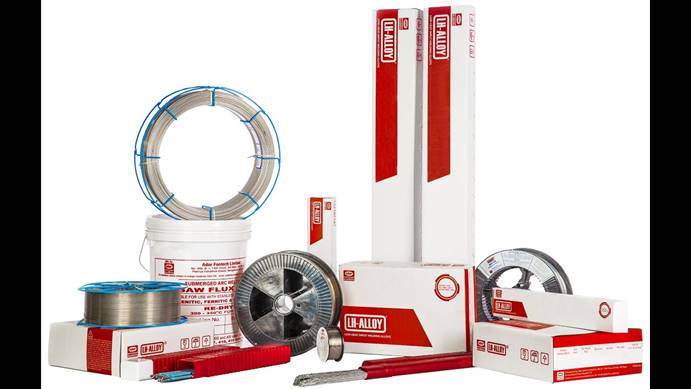
Brazing Rods are available in both ferrous and non-ferrous process for joining/welding different base materials.
Hence is widely used in industries for joining various components. ADFL serves the industry by manufacturing and supplying the entire range of Brazing products, suitable for use in all three processes.
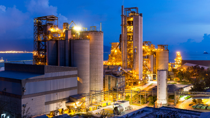
The cement industry is a vital part of the core sector that supports the world of infrastructure. One of the basic fulcrums which drives this process industry is maintenance and repair of cement Industry components.
Cement is manufactured from the raw material ore of limestone. The entire process starts from the mines and ends up as a final product in the Cement plant. This makes wear the underlying theme in the manufacturing of cement –primarily it is abrasive wear caused by hard limestone combined with impact, heat & erosion in the process
The modes of repair by welding can be divided into three types:
Protective maintenance of wearing components
Maintenance & repair of worn-out components
Breakdown repairs with highly reliable components
Now let us see the three types of repairs in detail to understand more about the welding of cement Industry components
Protective maintenance:
Manufacturing of cement involves handling hard limestone in very high abrasive conditions, with impact, heat, and erosion. In many cases, components making up the base material need protection. This can be as simple as wear protective welding of new components like earth moving buckets or rotary airlock valves with tailor made, ready-to-use wear solutions designed to give long life before they get worn out again, like Endurafon & Hardox ready-to-use wear plates.
Maintenance & repair of worn-out components:
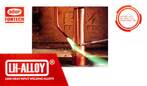
As the name itself suggests, this involves repair of the worn-out components with low heat input LH welding alloys to ensure prolonged life or improved life of the worn-out components. Repair & maintenance can also be defined in two parts.
Repair applications for joining components:
Typical applications include joining of anchor in Kiln, Pre-heater and cooler. This is an important application which supports castables in high temperature applications, as any damage or failure of castables will mean stoppage of plant, hence it is a critical application in any cement plant. ADFL’s LH 126 is widely used for this application across cement plants in India.
2. Application for Wear Protection:
The second one is built up & wear protection of wear prone components in the cement plant; Typical example is Buttoning of Sinter Cast rolls in VRM rollers and Roller Press Roll (RPR) pattern welding build up with Custom designed products to enhance life. LH WearTherm 65 is a product developed for this application & well appreciated for its longer life.
Breakdown Repair or Maintenance
Cement industry is a process industry hence certain components fail due to heavy loads, heat, material fatigue and it is difficult to carry an inventory for these components hence these components need in –situ repair ensuring maximum reliability and performance, some critical examples are kiln tyre or kiln girth gear repaired at site.
It is a matter of pride for Ador Fontech Limited that we are the first re-call for all Cement Industry customers when faced with breakdown of the plant in such applications. We have tailor-made solutions with specially manufactured Low Heat Input (LH) welding electrodes which provide the highest reliability and life enhancement. Our LH Gold 555 & LH 521 are key products which signify our capabilities.
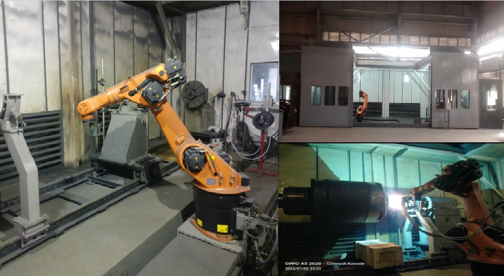
ADFL brings its 4 decades of experience in all types of applications in the Cement industry like joining, hard facing & cutting solutions required at customer premises. One of the key advantages with Ador is also our repair facility – our Life Enhancement Services facility in Nagpur. It is dedicated to the repair of all cement industry components, and also boasts a dedicated team to serve customers at their sites for all maintenance and welding repair solutions.
One of the key jobs we carry out through our LE services team at site is Kiln shell welding or kiln shell replacement. We carry out the Kiln shell welding process with a custom-built Automatic SAW welding process. This process gives highest reliability and productivity to customers and this process is 3 times faster than conventional repairs in the industry.
This is why the name Ador Fontech Limited is synonymous with total solutions for any Repair & Maintenance problems in the cement industry.
Advantages of Non-Fusion –Brazing and Soldering Process
Dis-advantages of Non-Fusion – Brazing and Soldering Process
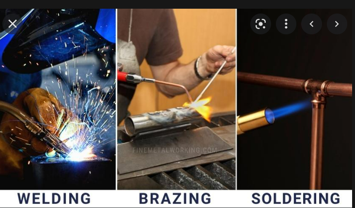
the key Difference between Welding, Brazing and Soldering
To understand the basic Difference between Welding, Brazing and Soldering we need to know about types of welding processes by principle.
Principle of Welding Processes:
Fusion welding
Welding done in liquid state without using pressure
Union is by molten metal bridging of mating surfaces
Principle of Brazing and soldering Process:
Solid phase welding
Welding done below the melting point without any filler additions
Pressure is often used in this type of welding
Union often occurs when material is in plastic flow
The Welding process is a Fusion process where as brazing and soldering are both solid phase welding processes.
Let us understand more about these three processes, which are widely used by many industries.
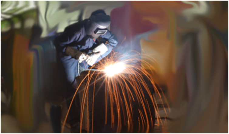
Welding / Shielded Metal Arc process (SMAW):
Shielded Metal Arc process is also known as manual metal arc welding process. In this process, an arc gets established between parent metal and a flux coated welding electrode using electrical energy. This arc melts the deposit weld metal and nn this process, actual melting of base metal and welding electrode bridges the gap and forms the welding This process is one of the most used welding processes in the world.
Basic Requirements for Welding / SMAW process:
Heat source – Welding Equipment Current Range 30-400 A –depending on size of electrode in general, even though welding machines that use up to 600 Amps AC as well as DC welding machines are equally useful in a SMAW Operation.
Welding Consumable: Flux coated welding electrodes (1.6- 8 mm diameter) are needed for the process along with a welder who is trained to manage the welding.
SMAW or MMAW is a commonly used welding process in the world.
Welding Process advantages:
Simplest of all welding processes
The equipment used is portable
Cost of equipment is economic
It has a variety of applications
There’s wide availability of electrodes
Can weld a wide range of metals & their alloys
Welding can be done from any position
Welding can be done indoors & outdoors
Welding cable extension goes very far
Limitations of welding process:
Low productivity as in a 10-minute cycle, welding happens only for 6 minutes
Process also involves frequent change of welding electrode
Moisture from flux coatings can create weld-related problems
Safety issues with arc strike, shocks from stray current/electric power
Process is completely manual as the name ‘Manual metal arc welding’ suggests
Soldering & Brazing:
In both the above processes joining happens by diffusion welding methodology, The joining happens through atomic diffusion of two surfaces in contact. Surfaces are usually heated to high temperature (below their melting point) & pressure may also be employed.
Soldering: Soldering as a process happens below 450 degrees Celsius Normally lead or tin based alloys are used for soldering
Brazing: This process happens between 450 degrees and 750 Degrees Celsius Silver & copper-based alloys are used for brazing.
Four Requirements of Non-Fusion Welding
Clean Surface: Non-fusion processes bond metal by adhesion, where adhesion happens to be the molecular attraction between bodies in contact.
Molecular bonding requires a clean surface.
Filler Rod:
Filler rods are used in many non-fusion processes.
Flux has applications in all non-fusion welding processes.
Purpose of flux:
Chemically cleans the metal
Shields weld from oxidation and atmospheric contamination
Heat Source
The heat must be sufficient (BTU”s) to raise the base metal temperature above the melting point of the filler rod.
To achieve this, several heat sources can be used.
Oxyacetylene
Air acetylene
Air propane (LPG)
Oxypropane
Electric soldering iron
Electric soldering gun
Advantages of Non-Fusion –Brazing and Soldering Process:
Lower temperature process
Easy assembly of parts
Welding dissimilar metals
Allows disassembly/realignment
Joins metals of different thicknesses
Joint different types of metal
Dis-advantages of Non-Fusion – Brazing and Soldering Process:
Lower tensile strength
Not an efficient method for thick metal
Not an efficient method for large parts.
So, the essential difference between Welding, Soldering & Brazing is as below.
Welding is a fusion process, where there is a homogenous bonding of joining surfaces.
While brazing and soldering are basically non-fusion processes which use diffusion to join materials.
All three processes have a wide variety of applications in industries depending on the uses and requirements. ADFL serves the industry with manufacture and supply of products in all three processes.
Sources of Heat Energy to Heat Powder, Wire & Rod Form
Flame Spray
Electric Arc Spray
Plasma Arc Spray
Kinetic Energy Processes
Types of Thermal Spray Coating Processes
Thermal Spray Principle:
“Thermal spray” consists of a family of processes that use thermal energy. The thermal energy may be generated by a chemical process like combustion or an electrical process involving plasma or arc methods so as to melt, or soften, and accelerate the fine dispersion of particles.
This process typically uses some amount of preheating but is otherwise just a kinetic energy process. Selection of the appropriate thermal spray method is based on the following:
Desired coating material
Coating performance requirements
Economics
Part size and portability
Basic Types:
Flame Spray
Flame Powder
Wire Flame
HVOF Coating
Electric Arc Spray
Plasma Arc Spray
Conventional Plasma
Vacuum Plasma
Kinetic Energy or Cold Spray process comes last.
Sources of Heat Energy to Heat Powder, Wire & Rod Form.
Flame Spray
Flame Powder: In the flame powder process, powdered feedstock is aspirated into the oxy fuel flame, melted, and carried by the
flame and air jets to the work piece. Particle speed is relatively low (<100 m/s), and bond strength of the deposits is generally lower than the higher velocity processes. Porosity can be high and cohesive strength is also generally lower
Wire Flame. In wire flame spraying, the primary function of the flame is to melt the feedstock material. A stream of air then atomizes the molten material and propels it toward the work piece
Substrate temperatures often range from 95 to 205 °C (200 to 400 °F) because of the excess energy input required for flame melting
High-Velocity Oxyfuel. In HVOF, a fuel gas (such as hydrogen, propane, or propylene) and oxygen are used to create a combustion jet at temperatures of 2500 to 3100 °C (4500 to 5600 °F).
The process results in extremely dense, well bonded coatings, making it attractive for many applications. Either powder or wire feedstock can be sprayed.
Electric Arc Spray
Electric Arc. In the electric arc spray process (also known as the wire arc process), two consumable wire electrodes connected to a high-current direct-current (dc) power source are fed into the gun and meet, establishing an arc between them that melts the tips of the wires.
The molten metal is then atomized and propelled toward the substrate by a stream of air. The process is energy efficient because all the input energy is used to melt the metal.
Electric arc spraying also can be carried out using inert gases or in a controlled-atmosphere chamber
Conventional plasma spray process: is commonly referred to as air or atmospheric plasma spray (APS).
Plasma temperatures in the powder heating region range from about 6000 to 15,000 °C (11,000 to 27,000 °F), significantly above the melting point of any known material.
To generate the plasma, an inert gas—typically argon or an argon-hydrogen mixture—is superheated by a dc arc. Powder feedstock is introduced via an inert carrier gas and is accelerated toward the work piece by the plasma jet.
Vacuum Plasma. Vacuum plasma spraying (VPS), also commonly referred to as low-pressure plasma spraying
At low pressures, the plasma becomes larger in diameter and length, and, through the use of convergent/divergent nozzles, has a higher gas speed
The absence of oxygen and the ability to operate with higher substrate temperatures produce denser, more adherent coatings with much lower oxide contents.
Kinetic Energy Processes
The latest advance in kinetic spraying is known as “cold spray.”
Cold spray is a material deposition process in which coatings are applied by accelerating powdered feedstocks of ductile metals to speeds of 300 to 1200 m/s (985 to 3940 ft/s) using gas-dynamic techniques with nitrogen or helium as the process gas
The process is commonly referred to as “cold gas-dynamic spraying” because of the relatively low temperatures (0 to 800 °C, or 32 to 1470 °F)of the expanded gas and particle stream that emanates from the nozzle
These are the commonly used process in Industry. We at ADFL have the complete infrastructure at our state of art facility – Life Enhancement Centre, Nagpur to facilitate maintenance & repair industry to carry out wide variety of jobs
Importance of controlling heat brazing & Key benefits with Flux-coated Brazing rods
Brazing Process
Flux coated brazing rods & their uses
Flux Coated Brazing Alloys And Their Requirements
Brazing is a part of non-fusion welding process where only the filler rod is melted. Brazing Rods are available as bare rods as well as flux coated brazing rods. Flux Coated Brazing Rods can be used for brazing & braze welding application.
Non-fusion Welding – Advantages & Disadvantages
Advantages
Lower temperature
Easy assembly
Weld dissimilar metals
Allows disassembly/realignment
Join metals of different thicknesses
Joint different types of metal
Disadvantages
Lower tensile strength
Not efficient method for thick metal
Not efficient method for large parts
Four Requirements of Brazing Process
Clean metal
Appropriate filler rod
Correct flux or Flux coated Brazing Rods
Heat
Clean Metal:
The brazing process bonds metal through a property called adhesion.- Where adhesion can be defined as the molecular attraction which is exerted between bodies when they come into contact.
Such bonding between molecules requires the surfaces to be clean, not polished.
Filler Rod
Brazing:
Brazing rods are available as bare rods or flux-coated brazing rods
Heat Source:
The heat must be sufficient (in BTUs) to raise the base metal temperature above the melting point of the filler rod to solder or braze the joint.
Several heat sources can be used.
Oxy acetylene
Air acetylene
Air propane (LPG)
Oxy propane
Electric soldering iron
Electric soldering gun
Flux:
Flux must be used with brazing processes.
Three purposes of flux.
Chemically clean the metal
Shield weld from oxidation and atmospheric contamination
Promote wetting
Choice of flux depends on both the metal and the filler material.
Flux comes in three forms.
Paste
Powder
Liquid
Advantages of Flux-coated Brazing Rods.
No external flux required
Addition of alloying elements
Better Bonding with uniform Flux
Better Properties as bonding achieved
Simpler process for welder
Importance of controlling heat brazing & Key benefits with Flux-coated Brazing rods
Metals are excellent conductors of heat
Heat applied to a joint is conducted away from the joint.
The heat required by the process depends on the amount of metal that needs to be heated.
Excessive heat causes the flux coating to burn
It can contaminate the joint.
Joint may need to be cleaned again
When we use flux-coated brazing rods, we can manage the application of heat to make it even ensuring controlled wetting and high-quality brazing properties.
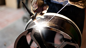
Brazing Process:
The brazing process uses a metal alloy that melts above 450oC, but less than the melting point of the base metal. The brazing process is aided by capillary action through which the filler metal gets drawn into the joint or stays in the joint. The capillary effect determines the ability of a liquid to wet a given material. This process is made possible by a very small gap between metal surfaces, clean surfaces, and flux.
Flux coated brazing rods & their uses.
Flux coated brazing rods are used for their capillary action and their ability to offer a higher build-up. Flux-coated silver brazing rods are used in close fit joints with capillary action.
Also, Cu based bronze and brass alloys are used to join thicker sections without capillary action. Flux coated brazing rods with tungsten carbides are used for hardfacing applications in industries. This process is called braze welding; In this process, the Brazing happens above 750⁰C but below the melting temperature of the base metal.
Unique advantages of flux coated brazing rods is that they can be used equally well in applications requiring capillary action and in applications that need higher build up or hardfacing through braze welding.
ADFL is first among the few companies in India that manufacture Flux Coated Brazing Alloys. This product range of Ador Fontech underlies our concept of Life Enhancement of Industrial components to the complete satisfaction of customers.
How Does Plasma Cutting Work? Advantages And Disadvantages
Plasma Cutting Process:
A plasma arc is super-hot and capable of melting metals instantly. This arc basically consists of ionized gas formed when electricity and pressurized gas combine. The gas shapes the arc and also blows away any excess molten metal, leaving a smooth cut edge.
Plasma cutting systems consist of :
A plasma cutting power source
Compressed air to enable cutting
Plasma Process – Advantages & Disadvantages:
To understand the advantages of Plasma Cutting process it’s essential to compare it to the conventional cutting process used in industry, namely the cutting process using oxyacetylene.
Plasma cutting using a plasma cutting power source with compressed air is useful for cutting all conductible material including both ferrous and non-ferrous materials, while in Oxyfuel cutting with a gas cutting torch, oxygen, and acetylene gas are used for cutting steel/ferrous material. This demarcates the major difference between the two processes.
So let us understand the basic intricacies of plasma cutter gas cutting or oxyfuel cutting in detail.
Plasma Cutting – Capabilities & Advantages:
Cut and gouge any electrically conductive metal like MS, SS, AL, alloys, etc.
Cut through rust, paint, coatings, and stacked metal
Cut with air. No gas, like acetylene or oxygen, required
Cut fast and clean up to 50mm, no pre-heating
“Plug and play” & drag-cutting features
Easy to use and automate
Small heat-affected zone
Can be used for cutting wire gauze or even filtering systems
Plasma cutting machines are available, and some of them offer portability
Plasma cutting with inbuilt compressor for all off-site applications
Faster process and easy to teach & train welders
Very safe process for both the welder and user
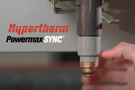
Some plasma cutting equipment like Hypertherm can operate on input voltage from 200 V to 600 V. This means the same machine can be used with single phase as well as three phase circuitries.
Plasma Cutting – Disadvantages:
Does not heat metal for bending
Initial investment is higher (but has good return on investment)
Does not efficiently cut much thicker than 75mm MS
Requires electrical energy or electricity for cutting
Requires compressed air for cutting
Slightly more complex settings in comparison to Oxyfuel cutting
Gas Cutting or Oxy-fuel Cutting Process:
Oxyfuel cutting torch heats ferrous material to ignition temperature with an oxygen/fuel gas flame. So, the high-pressure oxygen reacts with the metal to create iron oxide (slag) and blows and cuts the metal away.
In this process, a cutting torch, oxygen gas, and acetylene are primarily used for cutting.
The hazards caused by this process are:
Fire hazard from heat, sparks, molten metal or the flame itself
Explosions caused by cutting up or repairing containers that hold or used to hold flammable materials
Gas leaks, backfires and flashbacks causing fire or explosion
Fumes caused by flame cutting
Mishandling of oxygen resulting in fire/burns
Contact burns caused by the heated metal or flame
Impact injuries or crushing when handling and transporting cylinders
Gas Cutting or Oxy-fuel Cutting – Advantages:
Can effectively cut steel only
Most effective when cutting over 50 mm
Use anywhere cylinders are available
Relatively low initial acquisition cost
Heat metal for bending
Gas Cutting or Oxyfuel Cutting – Disadvantages:
Cuts only mild steel.
Metal must be pre-heated to pierce.
Hard to cut metal that is heavily painted, rusted, or stacked.
Much lower speed of cut compared to plasma
Hand cutting requires skill – standoff
Must use flammable gasses.
Metal warping and heat-affected zone
Summary:
Oxyfuel and plasma cutting are both reliable and established thermal processes used for cutting steel. Each offers it own advantages and disadvantages. Choosing one or the other would be entirely dependent on the specific needs of a business.
Oxyfuel requires the lowest capital and operating cost. But the costs per part, in the end, are higher due to its slow cutting speeds and lower cut quality, which often call for secondary operations. Oxyfuel is primarily used for cutting only thick carbon steel (greater than 50mm), provided its cut quality is not of any importance.
When we use Plasma, we get a good balance in terms of capital costs as well as an optimal mix of cut quality, productivity, and operating costs. It can offer the highest cutting speeds and material flexibility and can also cut through significant ranges of thickness.
For most hand-cutting applications today, industries are preferring plasma cutting, given that it is vitally important to ensure the safety and personal protection of the welder.
Ador Fontech Limited, a name synonymous with total Maintenance & Repair solutions, recommends Hypertherm plasma cutting with Duramax Torch and consumables as a robust plasma cutting solution to all our customers for any cutting and gouging application on their premises.
Remedies: Do’s for Welding Austenitic Stainless Steel
Stainless steel is the type of high alloy steel with at least 11.5% Chromium. Iron content exceeds that of any other element. Carbon is generally less than 1.5%.
Properties of Stainless Steel:
Mechanical Properties: Compared to other materials, stainless steel has strong mechanical properties at ambient temperatures, In particular, it combines ductility, elasticity, and hardness, In addition, it offers good mechanical behavior at both low and high temperatures. So widely used in all Industries.
Oxidation Resistance: Stainless steel has the best resistance of all metallic materials when used in structural applications, having a critical temperature above 800°C. Grades of Stainless steel can be used for Sub-zero temperatures.
Corrosion Resistance: With a minimum chromium content of 10.5%, stainless steel is continuously protected by a passive chromium oxide layer, This special feature gives stainless steel its resistance to corrosion.
Versatility: Stainless steel has a wide variety of finishes, from matte to bright, including brushed and engraved. It is widely used by architects for building envelopes, interior design, and street furniture.
Easy Maintenance: Stainless steel objects are easy to clean, and common cleaning agents.
Environment friendly: Stainless steel is the “green material” and is infinitely recyclable. It is environmentally neutral and inert when in contact with elements like water, and it does not release compounds that could change their composition.
Types of Stainless Steel Used in Industry:
AusteniticNon-Magnetic & work Hardening
Ferritic Soft & Magnetic
MartensiticMagnetic & Hard
Duplex Magnetic & Wok Hardening
Precipitation Hardening
Problems in Welding Austenitic SS:
Carbide Precipitation or IGC
Heat of Welding
Porosity
Contamination
Carbide Precipitation or Inter Granular Corrosion:
The major problem encountered in welding austenitic stainless steel is intergranular corrosion or carbide precipitation.
When welding Austenitic SSbetween 420 to 880 deg. C base metal temperature also known as “Sensitisation Temperature”a large volume of Cr is pickedin the grain Boundaries of the HAZ area
This forms Chromium Carbide which precipitates and forms at grain boundaries –the area adjacent to the HAZ area
So on working condition or in service, the HAZ area starts corroding at a faster rate as this area cannot form Cr2O3 due to Cr depletion
This phenomenon is called Inter Granular Corrosion or Carbide Precipitation
Remedies:
Controlling the carbon content (0.03% or below)
Addition of Carbide stabilizers like Ti, Nb.
Heat Treatment (Solution annealing).
Controlled welding below 450 Degrees
The heat of welding:
Cracking from the HAZ area
Loss of Corrosion Resistance
Warping or Distortion of Material
Loss of Mechanical Properties
Porosity :
This is caused by Dirt, Grease & marking material
Poor Quality of Flux coating
Contamination:
Contaminants in SS like Sulphur, Carbon, Iron, Copper & lead is the root Couse of failure of welded joints and also poor corrosion resistance
Remedies: Do’s for Welding Austenitic Stainless Steel:
Rigid Fixturing with more tack welds
Sequence welding to control heat
Baking of electrode 200 deg –one hour before welding.
Proper Cleaning of weld area before starting the job
Use short arc & low heat Input Welding Electrodes
Use Correct or optimum diameter electrode during welding
We at Ador Fontech have designed & developed this exclusive range of LH- Low heat Input Welding Electrodes, TIG & MIG wires for welding of all types of stainless including austenitic stainless steels.
Cast iron can be described as a wide variety of iron-based materials containing Carbon of 1.7%-4.5%
It also contains Silicon- 0.5%-3%, Manganese-0.2%-1.3%, Phosphorous-0.8% max & Sulphur -0.2%max. The major distinguishing feature between steels is carbon content, it has maximum influence on the property of CI. A low percentage promotes the formation of hard white cast iron & higher percentage promotes the formation of grey cast iron.
Properties of Cast Iron:
Hardness: Cast iron is hard and it can be hardened by heating and sudden cooling. This makes it quite durable.
Melting Point: Cast iron has a lower melting point (1200 deg. C) as compared to the melting point of mild steel which lies in the range of 1300 deg. C and 1400 deg. C.
Castability: Cast iron is easier to cast when it comes to casting shapes out of the material. Due to the extra carbon & silicon present in cast iron, its molten form is more fluid and this makes it easier to cast the material into complex shapes.
Machinability: Cast iron is almost elastic up to ultimate tensile strength and produces discontinuous chips which break away from the sample easily. This helps to improve the cutting ability. Due to this, cast iron is the preferred material when it comes to high machinability and strength.
Highly porous hence it can be used in machine bases etc. as it provides good self-lubrication properties as oil & grease remain in the porous mass of cast iron.
It’s Porous and sponge-like structure means it can be used in machine bases as it has good damping properties
Types of Cast Iron Used in Industry:
Grey Cast Iron
White Cast Iron
Chilled Cast Iron
Nodular Cast Iron
Malleable Cast Iron
Alloyed Cast Iron
Depending on carbon content and the procedure it is manufactured and these are common grades used in industry.
Problems in Welding Cast Iron:
CI is Brittle, so it tends to crack easily
Porous & Contaminated so cleaning is very tough
Too much Carbon tends to crack during welding
Lesser Heat Conductivity, so heat dissipation is fast
Carbon Pick up in the weld metal will be there leading to cracks in the HAZ.
Techniques to Weld Cast Iron.
Considering the above problems in cast iron, there are two methods or techniques to weld cast iron.
Hot Technique
Cold Technique
Hot Technique:
Preheat the cast iron component to 350 deg. C – 400 deg. C
Do the welding at the same temperature, ensure the temperature is maintained above 350 deg. C during the entire process of welding
Slow cool the welded component by gradually cooling the component, if the job was done with heating cold reduce 50 deg. C per hour for per inch thickness of the job, If done in a furnace switch off & allow it to cool.
Cold Technique
Limit heat input in the cast iron weldingjob by adopting the following methods :
Low current: Use low heat input welding electrodes & use lower diameter and lower amperages.
Stringer bead: Strictly no weaving during welding use only stringer beads
Short arc: Use arc length less than the diameter of electrode, preferable touch & weld type LH products
Short bead length: Weld not more than 25 -30mm bead length only, always weld with a job on hand heat
Peening: Hot peening with the ball-peen hammer is recommended for removing any residual stress in welding.
For welding of all weld-able grade cast iron, Nickel-based electrodes either pure nickel or Ferro-nickel type electrodes are used depending on the application requirements.
We at Ador Fontech have designed & developed this exclusive Range of LH Low heat Input Welding Electrodes for welding cast iron using both welding techniques required for cast iron welding
One of our most important manufactured products used in all industries has many applications & uses. Steel can be molded, pressed, machined, welded & woven to suit different purposes.
Steel making: It’s a three-step process.
Iron Making: Iron ore, coke & a flux (limestone) are combined in a blast furnace to produce molten iron containing about 4% carbon.
Steel Making: Excess carbon is removed in a basic oxygen steel making vessel and the required alloy is added. The molten steel is then cast into billets, blooms, or slabs.
Shaping: Steel is rolled to various sizes and shapes in a rolling mill.
Steels are basically a wide range of iron-based alloys with carbon up to 1 .7 %.
In plain carbon steels other elements are silicon (up to 0.6%), manganese(up to 1.65%), sulphur (up to 0.35%) & phosphorous (up to 0.13%).
1. Elements in Steel:
Carbon
Up to 1.7 %
Promotes formation of carbides (cementite, pearlite & martensite)
Manganese
Deoxidizes the metal and facilitates hot working
Neutralizes sulfur by forming manganese sulfide which increases strength
Provides work-hardening property
Silicon
Deoxidizes steel
Increases resistance to scaling
Phosphorous
An impurity
Decreases ductility and toughness
Sulfur
An impurity
Decreases strength and impact resistance
Improves machinability
2. Types of Steel :
Low Carbon Steels
Carbon up to 0.3 %
Good ductility & weldability
Comparatively low strength & not easily heat treatable
Welding: Have very good weldability.
No special precautions required
Medium Carbon steels
Carbon 0.3 to 0.6 %
Better strength & hardness than low carbon steel
Welding: Slight preheat around 200-250 deg. C and slow cooling.
Use a low hydrogen type electrode
High Carbon Steels
Carbon : 0.6 % to 1.71 %
Easily heat treatable to high hardness
Welding: Poor weldability.
Tendency to crack
High preheat around 300 deg. C and very slow cooling
Maintain high interpass temperature-300 deg. C
Post weld heat treatment and stresses relieving desirable
Alloy Steels
Contain alloying elements other than silicon, manganese, sulfur & phosphorous
High Alloy Steels
Alloying elements more than 10 % ( Ni, Mn, Cr)
Welding: High carbon equivalent hence form martensite.
Preheat around 300 deg. C and maintain interpass
Cool slowly
Low Alloy Steels
Alloying elements less than 10 %
Welding:Preheat requirements minimum.
Types of High Alloy Steels :
Austenitic Manganese steels:
More than 10 % manganese & high carbon
Known as Hadfield Steels
Work harden in service
Welding: Forms hard Carbides at temperatures above 175 deg. C.
No, preheat and fast cooling
Stainless Steels :
Chromium minimum 11.5 %
Excellent corrosion resistance
The addition of nickel gives good toughness & strength at sub-zero and elevated temperatures
Welding: Loose corrosion resistance on exposure over 500 deg. C
No, preheat and fast cooling
Low current & stringer beads
Tool Steels:
Used as Cutting Tools, Shear Blades, Dies, etc.
Contain high carbon
Have a high amount of tungsten, molybdenum, chromium, cobalt, etc., and withstand temperatures up to 550 deg.
Welding: Difficult to weld.
High preheat around 350 deg. C & cool slowly
Hence, we at Ador Fontech have designed & developed this exclusive range of LH low heat input welding electrodes, TIG rods & MIG wires to weld all types of steel used in industry, resolving all problems as the unique solution provider for maintenance & repair welding.
To join ferrous with non-ferrous metals, various methods can be adopted.
Mechanical methods: Fasteners, rivets, etc.
Adhesive bonding method: Brazing and Soldering (a.k.a. welding)
Base metal does not fuse: Molten filler gets drawn into close-fit joints through capillary action (surface tension forces).
Brazing filler melts at >450⁰C, soldering at <450⁰C
Welding is the most commonly used process of all.
Welding – A Definition
Welding can be described as a process of joining two or more pieces /edges of metal by producing a localized union through heat (fusion) with or without pressure to create a homogenous joint.
Types of Welding by Metal:
Autogenous: In this process, similar materials are joined without filler wire or electrode Heterogeneous: Process of joining dissimilar materials, using a filler wire or welding electrode
Metal Inert Gas welding or Metal Active Gas welding
SAW – Submerged Arc Welding
2. Solid-State and other Non-electric Fusion Welding: Examples of non-fusion, non-electric process welding are:-
Thermit welding
Ultrasonic welding
Diffusion welding
Deformation welding.
Welding Processes
Fusion welding: Welding in the liquid state with no pressure, Union is by molten metal bridging
Solid State welding: Carried out below the melting point of the metal without filler additions, Pressure is often used,
Union is often by plastic flow.
Solid State welding:
DEFORMATION WELDING: Two Surfaces in contact are brought into very close contact by applying high pressure, which deforms them. E.g., – Forge welding, Roll welding, Extrusion welding. (Not at very high temperatures)
DIFFUSION WELDING: Joining takes place by atomic diffusion of 2 surfaces in contact. Surfaces are usually heated to high temperatures (below the melting point) & pressure may be employed. E.g., Brazing, Braze welding & Soldering. Soldering is an oxy-fuel process of joining metals. The process temperature does not exceed 450⁰. Brazing is also an Oxy-Fuel joining process. The process temperature is between 450⁰ Degrees – 750⁰ degrees. Braze welding is similar to Brazing; the process temperature is above 750⁰ Degrees but below the melting point of the base metal.
Non-Fusion Process: Thermit welding is the most common process used in joining of railway tracks. In this process iron powders and Al binders are kept in Vat or a conical container above the joining rails. When they are fired due to chemical reaction and exothermic reaction, the iron powder melts and forms a joint between rails.
Introduction to Arc Welding: Basic welding processes used in Industry are
MMAW – Manual Metal Arc Welding or Shielded Metal Arc welding
GMAW – Gas Metal Arc Welding/ Flux Cored Arc Welding (MIG, MAG)
GTAW – Gas Tungsten Arc Welding (TIG)
SAW – Submerged Arc Welding
MMAW or SMAW- Shielded Metal Arc process: In the Shielded Metal Arc process or Manual metal Arc welding process the arc is established between Parent Metal and a flux coated welding electrode using electrical energy to melt and deposit weld metal. This is the most commonly used process in the world.
Basic Requirements for the SMAW process:
Heat source: Welding Equipment Current Range 30-400 A –depending on size of the electrode in general, even though there are welding machines used up to 600 Amps AC or DC welding machines can be used in SMAW Operation.
Welding Consumable: Flux coated welding electrode (1.6- 8 mm diameter)
A trained welder is required to operate the process, So SMAW or MMAW is the most commonly used process in the world.
SMAW Process advantages:
This is the simplest of all welding process.
Equipment Portable
Economical Cost of Equipment
Variety of application & wide availability of electrodes
Range of metals & their alloys can be welded
Welding in all Positions
Welding in Indoor & Outdoors
Extended welding cable to long distances in comparison to another process
Limitations of SMAW process:
Low productivity as in a 10-minute cycle welding happens only for 6 minutes
Process also involves a frequent changes of welding electrode
Moisture from flux coatings can create weld-related problems
Safety problems like arc strike, Stray current & electric shock risks
Absolutely Manual process – hence called Manual metal arc welding
GMAW & FCAW processes:
A continuous solid wire, small diameter
GMAW uses solid wire, no flux
FCAW use flux-filled wire
Wire feed through the gun to the arc by wire feeder.
Weld pool may be protected from oxidation by shielding gas.
High productivity 3 kg/h or more
Direct current (DCEP mostly).
Process Requirement:
Welding power source
Wire feeder mechanism- In-built/separate
Gun with gas supply & trigger switch
1. Manual/semi-automatic guns
2. Automatic torches available
3. Can be fitted to automation etc.
Advantages in GMAW:
Faster as compared to TIG & SMAW.
Can produce joints with deep penetration.
Thick & thin, jobs can be welded effectively.
Can be used for fabrication and maintenance repair job.
Can be mechanized easily
Reduced distortion.
Limitation in GMAW:
More Complex due to
Electrode stick-out
Torch angle
Welding parameters
Type and size of electrode
Welding torch manipulation
Not suitable for outdoor welding applications
GTAW or TIG welding: GTAW or Tungsten Inert gas welding uses a consumable Tungsten electrode as the heat source.
This consists of the below. Heat source – welding power source to create an arc between a tungsten tip and the parent metal
30-400A, AC or DC welding machine and 0-20V
Inert gas shielding is used in the process. Consumable: filler rod can be used between 1 to 4mm diameter Process Features:
Excellent control
1. Stable arc at low power (80A at 11V)
2. Independently added filler
3. Ideal for intricate welds eg root runs in the pipe or thin sheet
4. Low productivity 0.5kg/h manual
High quality
1. Clean process, no slag
2. Low oxygen and nitrogen weld metal
3. Defect-free, excellent profile even for single-sided welds
Advantages in GTAW/TIG Process:
No slag inclusion
Clear visibility of arc and job
All position weldability
Suitable for high quality welding of thin material
Root run of thick materials
Ideal for Aluminum, Stainless steel & Titanium
Limitations in GTAW:
Slow as compared to SMAW/MIG/MAG & SAW welding
Possibility of tungsten inclusion in the weld deposit which is hard & brittle
Not suitable for outdoor welding
Submerged Arc welding process (SAW Process): In the Saw Process, as the name signifies, welding happens submerged beneath the flux. SAW process also employs welding consumables usually a wire & arc is established between the welding wire and base metal and welding happens underneath the metal powder of flux, shielding the arc from the atmosphere and its gases.
Heat source: Arc between a wire and base metal Current Range: 200 Amps -1200 Amps
DC operation Power Consumption
35-56 KVA
Power source
Welding head and control box
Welding head travel
Flux recovery system (optional)
Positioners and Fixtures
Hence the basic difference between the two processes is that in the SMAW process, the flux-coated electrode provides the shielding from the atmosphere & in SAW process an external flux is delivered at the arcing area to act as a shield, so welding happens underneath the powder flux fed by a delivery system.
SMAW Process – Advantages:
Simplest of all Arc welding process
Equipment is portable
Economical cost of equipment
Variety of application & wide availability of electrodes
Range of metals & their alloys can be welded
Welding in all Positions
Welding in Indoor & Outdoors
Extended welding cable to long distances when compared to other processes
SAW Process advantages:
High productivity up to 2 to 10 kg per hour
Speed almost up to 2m/ min
Can be easily automated for even higher productivity
Limitations of the SAW process:
Bulky, expensive, and heavy equipment
Flat and horizontal positions only
Thicker sections (6mm and above)
Mostly ferrous materials (also Ni alloys)
Conclusion: A wide variety of processes are available for joining or hard surfacing ferrous and non-ferrous materials. Each of these processes provides different mechanical properties and works in specific conditions, with a welding power source. There are several factors to consider in welding rod selection:
Base metal properties
Tensile strength required
Welding current
Base metal thickness, shape and joint fit-up
Welding position
Specification and service conditions
No. of similar jobs – Scope for automation
Environmental job conditions
These methods are all commonly used by Industry. Before we select any particular method for welding, we need to analyze each of the factors listed above.
ADFL serves the industry with the manufacture and supply of all types of consumables for MMAW, MIG /Mag, TIG, SAW & non-fusion processes like soldering, brazing, and braze welding. This is why Ador Fontech’s name is synonymous with total solutions for any maintenance & repair problem, ensuring the Life Enhancement of Industrial components, to the complete satisfaction of customers.


 It also contains Silicon- 0.5%-3%, Manganese-0.2%-1.3%, Phosphorous-0.8% max & Sulphur -0.2%max. The major distinguishing feature between steels is carbon content, it has maximum influence on the property of CI. A low percentage promotes the formation of hard white cast iron & higher percentage promotes the formation of grey cast iron.